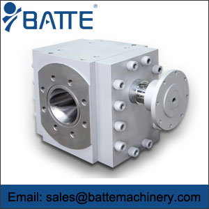
Extrusion gear pump principle and built structures
Gear pump structure, it is very simple, that is, it is the most basic form of two of the same size gear in a close coordination of casing gears rotate, the shell's internal similar "8" glyph, two gear is installed inside, outside diameter of the gear on both sides and work closely with shell.

Extrusion gear pump image.
The material from the extruder enters into the middle of the two gears at the suction inlet and fills the space with the rotation of the teeth moving along the shell, and finally out when the two teeth are engaged. In terms of terminology, the gear pump is also called a positive displacement device, which is like a piston in a cylinder. When a tooth enters the fluid space of another tooth, the liquid is mechanically squeezed out. Because liquids are incompressible, liquids and teeth can't occupy the same space at the same time, so the liquid is eliminated. Due to the constant meshing of the teeth, this phenomenon is continuously occurring, thus providing a continuous discharge of the pump's outlet, which is the same amount of output per rotation.
With the constant rotation of the driving shaft, the pump also pumps out the fluid continuously. The flow of the pump is directly related to the pump speed. In fact, the extrusion gear pump is very small amount of fluid loss, which makes the operation efficiency of the pump can't reached 100%, because the fluid is used for lubrication bearing and gear on both sides, and the pump body is impossible without clearance fit, so cannot make fluid 100% from an outlet, so a small amount of fluid loss is inevitable. However, the extrusion gear pump can still operate well, and can still reach 93% ~ 98% efficiency for most extruded materials.